Current location:
Common Wire Processing Problems and Practical Solutions
2026-09-22Every wire mill has its recurring defects—the ones that appear in batches, cost hours of scrap sorting, and sometimes reach the customer before they are detected. When these defects are treated as random events and addressed only when they occur, they become chronic production problems that consume engineering time and erode profitability. The alternative is systematic defect analysis: understanding that each defect type has specific causes, establishing the diagnostic indicators that point to those causes, and implementing the corrective actions that address the root cause rather than just the symptom. Wire processing problems are solvable problems once they are understood correctly.
Die Lines: The Most Common Wire Surface Defect
Die lines are longitudinal surface scratches or grooves that run parallel to the wire axis and are replicated at every point along the wire where the defect source has been in contact with the die bore. They are the most frequently encountered surface defect in wire drawing, and their cause can almost always be traced to one of three sources: inadequate lubrication, die bore surface degradation, or lubricant contamination.
The diagnostic approach to die lines begins with examining the wire surface under good lighting to characterize the defect. Fine, uniformly distributed die lines that appear across the entire wire surface and throughout the production run typically indicate emulsion breakdown or contamination—something is degrading the lubrication film that separates the wire surface from the die bore. Coarse, isolated die lines that appear intermittently or in specific locations on the wire surface typically indicate die bore damage—scratches, pick-up, or erosion in the die that are being replicated on the wire.
For lubrication-related die lines, the investigation proceeds to the emulsion system. Is the concentration correct? Is the temperature within specification? Is there evidence of bacterial contamination—the slimy deposits and distinctive odor that indicate bacterial growth in the emulsion? Is the emulsion clean, or are there tramp oils, metal fines, or scale particles visible on the emulsion surface or settled in the tank? Any of these conditions can cause the die line defect by rupturing the lubrication film and allowing metal-to-metal contact between the wire and die bore.
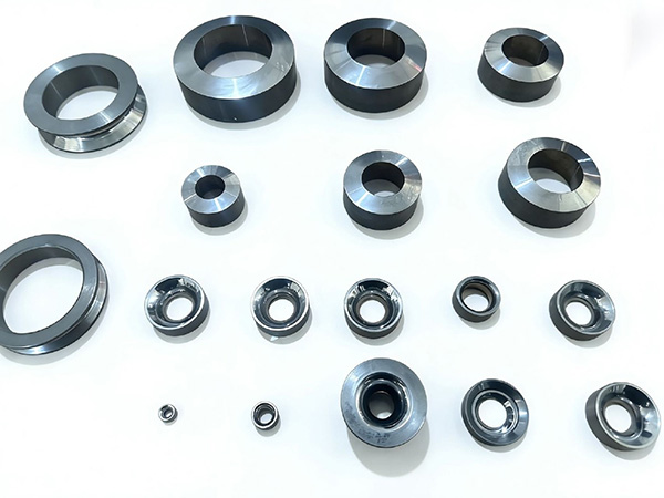
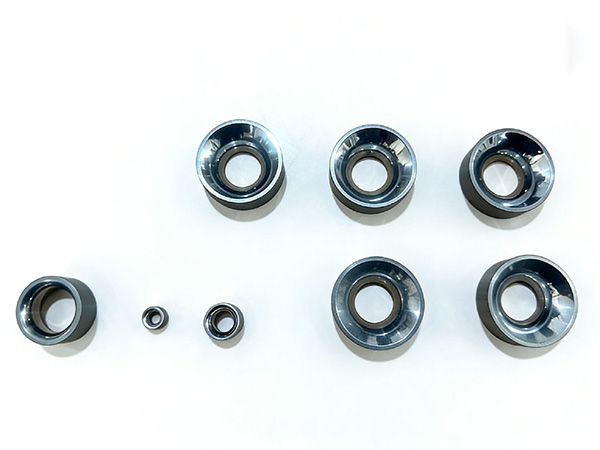
For die bore damage-related die lines, the investigation proceeds to die inspection. Examine the die bore under magnification—typically 10x to 50x is sufficient for initial assessment—for scratches, embedded particles, surface pitting, or areas where the polishing has been worn away. The location of the die line on the wire surface can help locate the corresponding damage in the die bore: a die line on the top of the wire corresponds to damage in the bottom of the die bore, and vice versa, because the wire rotates as it passes through the die.
Corrective Actions for Die Lines
The corrective action for lubrication-related die lines depends on the specific lubrication problem identified. Emulsion concentration correction requires adjusting the mix ratio and verifying with a refractometer. Bacterial contamination requires full emulsion dump and tank cleaning followed by fresh emulsion mixing. Tramp oil contamination requires identifying and eliminating the oil source and improving skimmer or coalescer performance. Contamination with solid particles requires filtration improvements or emulsion replacement.
The corrective action for die bore damage-related die lines is die maintenance. For minor surface damage, die repolishing can restore the bore surface to acceptable condition. For significant damage—deep scratches, pitting, or adhesive wear patterns—the die may need to be stripped to remove the damaged surface layer and repolished from scratch. A die with excessive damage should be removed from production rather than allowed to generate defective wire.
Wire Breaks: Diagnosing Break Location and Morphology
Wire breaks in wire processing are more costly than surface defects because they stop production, require time to restart, and may generate tangled scrap that cannot be rethreaded. A systematic approach to break analysis identifies the break type and traces it to its root cause, which then points to the appropriate corrective action.
The first diagnostic step is examining the break morphology—the shape of the break surface. A break with a clean, cup-and-cone morphology—the classic fracture surface of a ductile material under tensile overload—indicates that the drawing force exceeded the wire's tensile strength at the break location. This is typically caused by an excessive reduction ratio in the current pass, a reduction that is too large for the material's ductility at that point in the reduction schedule, or a reduction schedule that has been disrupted by a previous pass producing oversized or damaged wire.
A break with a flat, shear-type fracture surface indicates a different cause—typically a die bore problem or accumulated surface damage. If the break occurs immediately downstream of the die exit, the back relief geometry may be inadequate for the drawing conditions, creating stress concentrations that cause the wire to shear off at the exit. If the break occurs after several meters of production, accumulated surface damage from previous passes or from inadequate lubrication in the current pass has weakened the wire until it can no longer sustain the drawing load.
A break that initiates from a surface defect—a visible notch, seam, or inclusion at the break origin—indicates a material or prior-process problem rather than a current-process problem. The defect that caused the break was present in the wire before it entered the current die, and the drawing process simply revealed a pre-existing problem. Tracing this type of break requires examining the production history: which pass did the wire come from, what was the condition of that die, and what was the surface quality of the wire before the current pass.
Central Burst: A Specific Metallurgical Defect
Central burst is a specific wire break type characterized by a circumferential crack at the center of the wire that propagates outward through the wire cross-section. It is a metallurgical defect caused by excessive tensile hydrostatic stress at the wire center during drawing—the center of the wire is in tension while the surface is in compression, and if the center stress exceeds the material's ductility, a crack initiates and propagates radially.
Central burst indicates that the reduction ratio in the current pass is too large for the material's condition. This can occur when the starting material has reduced ductility from previous processing—for example, work-hardened wire that has been aged or has absorbed hydrogen. It can also occur when the reduction schedule is changed without accounting for the material's current condition, or when a die is running oversized and the subsequent pass must take a larger-than-intended reduction to compensate.
The corrective action for central burst is to reduce the reduction ratio in the pass where the break occurred and in subsequent passes until the material ductility recovers. If central burst recurs at the same reduction across multiple material lots, the reduction schedule itself needs to be reviewed and the reductions redistributed to smaller per-pass values.
Dimensional Problems: Out-of-Tolerance Wire
Dimensional problems in wire processing—wire that is too large, too small, or out-of-round—typically originate from die geometry changes, process instability, or material variability. Each of these sources has characteristic signatures that help distinguish them during diagnosis.
Wire that is consistently oversized and continues to grow larger throughout the production run indicates die wear. The die bore diameter increases as the bearing surface wears, and the wire drawn through it grows correspondingly. The wear rate depends on the drawing speed, the material being drawn, the lubricant quality, and the die material—carbide dies wear slower than tool steel, and PCD dies wear slowest of all. Tracking wire diameter over the production run and plotting it against production output identifies the die wear rate and predicts when the die will reach its wear limit.
Wire that is consistently oversized from the first pass indicates a die that was manufactured oversized or a die that has expanded thermally beyond its operating specification. Dies that are undersized from the start are less common because die manufacturers typically hold bore dimensions to the target or slightly undersized, allowing the die to be adjusted outward if needed.
Out-of-round wire—wire with elliptical or irregular cross-section—indicates a problem with the die bore geometry or with the wire handling downstream of the die. A die with an out-of-round bore produces out-of-round wire directly. A die with adequate bore roundness can produce out-of-round wire if the wire is bent, flattened, or distorted by guides, rollers, or spooling equipment downstream of the die. Distinguishing between these causes requires measuring the wire at multiple points around its circumference at the die exit and comparing it with the wire shape downstream.
Process Instability and Dimensional Drift
Dimensional drift—wire that gradually grows or shrinks during a production run without the die geometry changing—indicates process instability rather than die wear. The most common cause is temperature variation in the die or the wire. As the die temperature increases during a production run, the die bore expands and the wire diameter grows. As the wire temperature changes along the production line, its thermal expansion and contraction affect the measured diameter.
Controlling dimensional drift requires controlling the temperature environment of the die and the wire. Die cooling systems, when properly designed and maintained, maintain die temperature within a narrow range throughout the production run. In-line diameter measurement with feedback control can compensate for minor thermal drift by adjusting the drawing speed or die position to maintain the target diameter. These control systems are standard in high-precision wire production and are increasingly common in standard gauge production as quality requirements tighten.
Surface Contamination and Material Adhesion
Wire surface contamination—particles of material adhering to the wire surface, discoloration from oxidation or lubricant residue, or embedded particles that create surface defects—indicates problems in the lubrication system, the die bore, or the wire handling equipment upstream of the die.
Material pick-up on the die bore surface—small fragments of wire material that adhere to the die and create a raised spot in the bore—is a common cause of surface contamination. Pick-up occurs when the lubrication film ruptures, allowing the wire surface to make direct contact with the die bore. The contact welds a small fragment of wire material to the die surface, and that fragment then scratches the wire surface continuously until it is removed. Pick-up is most common in high-speed drawing of materials with high surface energy—stainless steel, nickel alloys, and some aluminum alloys—where the adhesion tendency is higher than in carbon steel or copper.
Removing pick-up from the die bore requires careful polishing to remove the embedded fragment without damaging the surrounding bore surface. If the pick-up is extensive or recurs frequently, the underlying cause—usually inadequate lubrication or incorrect die geometry for the material being drawn—should be addressed rather than just treating the symptom.
Accumulated Damage in Multi-Pass Wire Drawing
In multi-pass wire processing, defects from earlier passes accumulate and propagate through subsequent passes. A surface scratch from pass one becomes a crack initiator in pass five. A die line from inadequate lubrication in an early pass creates a stress concentration that leads to a break in a later pass at higher reduction. Managing accumulated damage is as important as managing individual process variables.
The concept of "good wire in, good wire out" applies to each pass in the reduction schedule. Each die must produce wire that is properly prepared for the next pass—not just dimensionally acceptable but surface-clean and stress-free enough to handle the subsequent reduction without accumulating additional damage. A die that is running at the edge of its capability may produce dimensionally acceptable wire while leaving surface or subsurface damage that shows up as breaks in downstream passes.
Managing accumulated damage requires process control discipline: monitoring surface quality at each pass, not just at the final pass; replacing dies before they generate surface damage that propagates through subsequent passes; and maintaining the lubrication system to standards that prevent defect generation at every pass, not just at the critical ones.
Establishing a Wire Processing Problem Resolution Process
Effective wire processing problem resolution requires a structured approach that moves from observation to diagnosis to corrective action to verification. This process should be documented so that it is applied consistently and the results are tracked over time.
Observation begins with characterizing the defect: what does it look like, where on the wire surface does it appear, when during the production run does it appear, and how frequently does it occur. This information narrows the range of possible causes and directs the investigation to the most likely sources.
Diagnosis tests the hypotheses generated by the observation. Check the lubrication system first—it is the most common cause of wire surface defects. Check the die next—bore damage, wear, and geometry problems are the next most common. Check the process parameters third—reduction ratios, drawing speeds, and temperatures. The investigation should proceed in order of probability, ruling out causes systematically until the root cause is identified.
Corrective action addresses the root cause, not just the symptom. Replacing a worn die without investigating why it wore prematurely, or changing the emulsion without fixing the contamination source, treats the symptom and guarantees the problem will recur. The corrective action should include steps to prevent recurrence—process changes, equipment modifications, or maintenance procedure improvements that eliminate the root cause.
Verification confirms that the corrective action resolved the problem. Monitor the production run following the corrective action to confirm that the defect no longer occurs. If the defect recurs, the corrective action was incomplete and the investigation must continue.
Frequently Asked Questions
Q1: What is the most common cause of die lines in wire drawing?
Lubrication system problems cause the majority of die lines in wire drawing. Emulsion breakdown from incorrect concentration, temperature, or bacterial contamination ruptures the lubrication film and allows metal-to-metal contact between the wire and die bore, creating scratches that appear as die lines on the wire surface. The second most common cause is die bore surface damage from wear or pick-up.
Q2: How do I distinguish between a material problem and a die problem when a wire breaks?
Examine the break morphology and the wire surface upstream of the break. A break that initiates from a surface defect—visible seam, inclusion, or notch—indicates a material or prior-process problem. A break with uniform cup-and-cone morphology without a visible initiation point indicates an excessive drawing force, typically from a reduction that is too large for the material's current condition.
Q3: What does out-of-round wire tell me about the production process?
Out-of-round wire at the die exit indicates die bore geometry problems—the bore is not circular, so the wire cannot be. Out-of-round wire downstream of the die indicates wire handling problems—guides, rollers, or spooling equipment are distorting the wire after it exits the die. Measuring the wire shape at multiple points along the production line identifies where the distortion originates.
Q4: How do I know if central burst is caused by the die or the material?
Central burst is a metallurgical defect caused by excessive center tensile stress during drawing. It occurs when the reduction ratio is too large for the material's current ductility. If central burst occurs consistently across multiple material lots at the same pass, the reduction schedule should be reviewed. If it occurs with one material lot but not others, the material's ductility in that specific lot should be investigated.
Q5: How can I prevent wire processing problems from becoming chronic?
Prevent chronic wire processing problems by establishing systematic defect tracking, diagnosing each defect to root cause, implementing corrective actions that address the root cause, and verifying that the corrective actions work. Track defect rates by die, by material lot, and by process parameter to identify patterns before they become chronic problems. Replace dies on a schedule based on production output and surface quality data, not just when they fail.
Conclusion
Wire processing problems are solvable. Die lines, wire breaks, dimensional problems, and surface contamination each have specific causes that can be identified through systematic diagnosis and corrected through targeted actions. The alternative—treating defects as random events and responding only when they occur—guarantees that they will become chronic problems that drain engineering time and erode production profitability. Building a defect resolution process that moves from observation through diagnosis to corrective action and verification, and tracking the results over time, transforms the approach to wire quality from reactive to proactive and delivers the consistency that customers require.
References
Richardson, J. H., & Martinez, C. A. (2023). Die Wear Mechanisms in Wire Drawing: Effects of Lubrication Regime and Die Material. Wear, 518-519, 204618.
Wright, R. N., & Bae, N. (2023). Lubrication Mechanisms in Fine Wire Drawing Processes. Journal of Manufacturing Science and Engineering, 145(6), 061010.
Zhang, Y., & Chen, L. (2022). Process Optimization for Precision Wire Drawing: A Review. International Journal of Advanced Manufacturing Technology, 120(7), 4821-4840.
Kalpakjian, S., & Schmid, S. R. (2022). Manufacturing Engineering and Technology (8th ed.). Pearson.
ASM International. (2022). Failure Analysis and Prevention. Materials Park, OH: ASM International.