Current location:
The Role of Drawing Dies in Wire Manufacturing Processes
2026-06-25Drawing dies are the precision tooling at the heart of virtually every wire manufacturing operation worldwide. From electrical copper conductors to high-strength steel cables, from medical guidewires to jewelry chains, the wire that powers modern industry is shaped, sized, and surface-finished by passing through one or more wire drawing dies. Understanding the role these components play in wire manufacturing is essential for engineers, production managers, and procurement professionals responsible for wire product quality, efficiency, and cost management. This article provides a comprehensive technical overview of how drawing dies function within the wire production process and why their specification matters.
Wire Drawing: The Fundamental Manufacturing Process
Wire manufacturing through drawing is a cold-working process that reduces the cross-sectional area of metal rod or wire by pulling it through a die with a smaller bore diameter. As material passes through the die, it undergoes plastic deformation—the crystalline structure rearranges, the cross-section decreases, and the length increases proportionally. The die geometry controls exactly how this deformation occurs and what properties the resulting wire exhibits.
The reduction ratio per pass typically ranges from 10% to 45% of the incoming cross-sectional area. Multiple passes through progressively smaller dies transform thick rod (typically 5–12mm diameter) into finished wire ranging from coarse structural wire (3–8mm) to ultra-fine wire below 0.02mm. Throughout this multi-stage reduction sequence, drawing dies are the only components that directly contact the wire and determine its final characteristics.
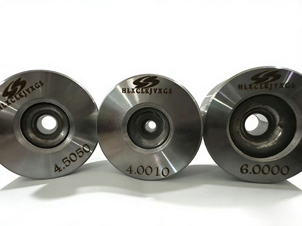
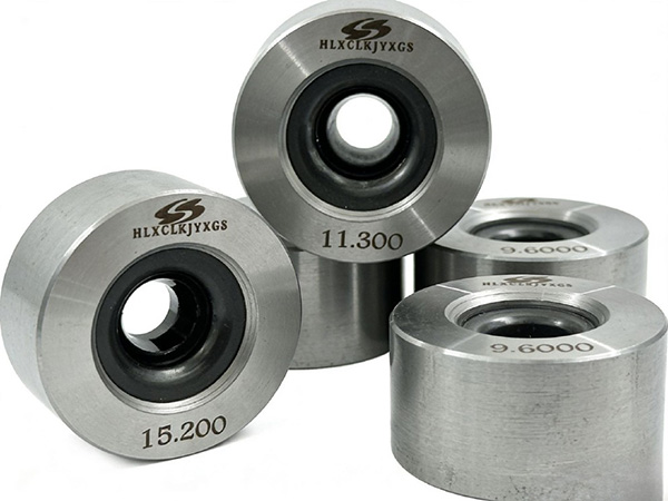
Primary Functions of Drawing Dies in Wire Production
Drawing dies serve several critical functions in wire manufacturing, each directly impacting wire quality and production economics.
Dimensional control is the most obvious function. The die bore diameter at the bearing zone determines the wire diameter exiting the die. Since downstream operations—spring coiling, fastener heading, cable stranding—are designed around specific wire diameters, the die is the quality gate that must hold diameter within tolerance. Typical industrial wire diameter tolerance ranges from ±0.5% for general applications to ±0.1% for precision applications.
Surface finish generation is equally important. The die bore surface texture directly transfers to the wire surface. A precision-polished die bore produces wire with mirror-quality surface finish; a rough or worn die produces wire with surface defects, die lines, and dimensional variation that cause problems in subsequent processing and end-use performance.
Mechanical property development occurs as the wire undergoes work hardening during drawing. The reduction ratio, approach angle, and bearing length of the die influence how the material's crystal structure deforms, affecting tensile strength, yield strength, and ductility. Proper die specification ensures the drawn wire exhibits the mechanical properties required for its intended application.
Die Geometry and Its Impact on Wire Quality
The internal geometry of a drawing die is not simply a hole through which wire passes—it is a precisely engineered profile with multiple functional zones.
The bell or entry zone guides incoming wire smoothly into the die without shock. Its geometry affects wire centering and prevents surface scoring from misalignment. The approach or reduction zone is where the primary deformation occurs. The included angle (typically 12°–30°) determines the deformation pattern: narrower angles reduce drawing force but concentrate wear; wider angles distribute wear but increase force and risk of internal defects. The bearing or sizing zone controls final diameter. Its length (typically 30–60% of wire diameter) affects dimensional precision and friction. The exit relief prevents the freshly drawn wire from contacting the die wall, which could scratch the surface.
Optimizing this geometry for specific wire materials and reduction ratios is a core competency of experienced die manufacturers. Research published in the Journal of Manufacturing Science and Engineering demonstrates that proper geometry optimization can reduce drawing force by 15–25% while maintaining dimensional tolerance—improvements that directly translate to energy savings and longer die life.
Die Materials and Their Selection for Wire Manufacturing
Material selection for drawing dies depends primarily on wire type, diameter, and production volume. Tungsten carbide dies dominate general-purpose wire manufacturing for diameters above 0.5mm. Their combination of hardness, toughness, and cost-effectiveness makes them suitable for steel, stainless steel, copper, and aluminum wire across most industrial applications.
Polycrystalline diamond (PCD) dies excel in non-ferrous wire production, particularly copper magnet wire, where superior surface finish is essential for insulation adhesion. PCD dies typically last 3–5 times longer than carbide in equivalent applications, justifying their higher cost for high-volume production.
Natural diamond dies remain the choice for ultra-fine wire below 0.1mm, particularly for precious metals and specialty applications where no other material can achieve required surface quality and dimensional precision.
Lubrication: The Critical Partner to Drawing Die Performance
The role of drawing dies in wire manufacturing cannot be separated from the role of lubrication. Lubricant forms a boundary layer between the wire surface and die bore, reducing friction, carrying away heat, and preventing metal-to-metal contact. Without adequate lubrication, even the finest die produces poor-quality wire and fails prematurely.
For steel wire drawing, dry lubricants—soap-based compounds carried by borax or phosphate coatings on the wire surface—provide the necessary boundary film. For copper and aluminum, wet drawing uses emulsion-based lubricants that cool and lubricate simultaneously. The lubricant film thickness must be carefully controlled: insufficient lubrication causes surface defects and accelerated die wear; excessive lubrication causes hydrodynamic pressure that distorts wire geometry.
Die Maintenance and Lifecycle Management
Effective wire manufacturing requires systematic die lifecycle management. Dies gradually wear as they process wire—the bore diameter slowly increases, surface polish degrades, and geometry drifts from specification. Without monitoring and scheduled replacement, this wear eventually produces out-of-tolerance wire that must be scrapped.
Modern wire drawing lines incorporate in-line diameter measurement that continuously monitors wire size and alerts operators when diameter drift indicates die wear. This enables scheduled die changes during planned maintenance windows rather than reactive replacement after scrap-generating quality failures.
For carbide dies, reconditioning extends service life at a fraction of new-die cost. A structured reconditioning program—tracking each die's bore diameter, reconditioning history, and recommended application—maximizes the value extracted from every die purchased.
Emerging Trends in Drawing Die Technology
Advanced wire manufacturing operations increasingly adopt coated carbide dies—physical vapor deposition (PVD) coatings such as TiN, TiAlN, or diamond-like carbon (DLC) that enhance surface hardness and reduce friction. These coatings can extend carbide die life by 30–60% in abrasive applications, particularly stainless steel and high-carbon steel wire.
Simulation-optimized die design is another trend gaining traction. Computational fluid dynamics (CFD) and finite element analysis (FEA) enable die geometries to be optimized virtually before steel is cut, reducing the number of physical iterations required to achieve target performance. For complex wire profiles and high-value wire products, simulation-optimized dies accelerate time-to-market and improve first-run yields.
Frequently Asked Questions
Q1: How many drawing dies are typically needed to reduce wire from rod to finished size?
The number of passes depends on starting rod diameter, target wire diameter, and the reduction ratio per pass achievable for the wire material. Typical sequences range from 6–12 passes for steel wire (starting from 5.5mm rod to 1–3mm finished wire) and 10–20 passes for fine copper wire (starting from 8mm rod to below 0.3mm). Each pass requires a dedicated drawing die.
Q2: What causes premature drawing die failure?
Common causes include abrasive wear from hard wire materials, thermal fatigue from high-speed drawing without adequate cooling, mechanical damage from wire threading errors or misalignment, and lubricant breakdown. Proper die specification for the application and adherence to recommended operating parameters minimize these failure modes.
Q3: How does die material affect wire surface quality?
Diamond dies can be polished to Ra below 0.02 μm, producing wire with exceptional surface quality suitable for critical applications. Carbide dies typically achieve Ra of 0.05–0.15 μm, excellent for most industrial applications but not matching diamond's mirror finish. The die material's ability to hold a polish directly determines the wire surface it produces.
Q4: Can the same die be used for different wire materials?
Generally not recommended. Different materials have different hardness, friction characteristics, and optimal drawing parameters. A die optimized for copper will not perform optimally for steel, and cross-contamination between material types can affect wire surface quality. Best practice dedicates dies to specific wire materials.
Q5: What is the relationship between drawing speed and die wear?
Higher drawing speeds generate more heat at the wire-die interface, accelerating wear if cooling is inadequate. Speed also affects lubricant film formation—too fast can cause lubricant breakdown; too slow may not establish adequate film thickness. Optimal speed balances productivity against die life for the specific application.
Conclusion
Drawing dies are the precision instruments that determine wire dimensional accuracy, surface quality, and mechanical properties in wire manufacturing. Their geometry, material, surface finish, and maintenance directly control production quality and efficiency. Engineers and procurement professionals who understand the role of drawing dies in the wire production process are better equipped to specify appropriate tooling, select capable suppliers, and implement lifecycle management practices that maximize the value extracted from every die. In an industry where tolerances tighten continuously and customer quality expectations rise relentlessly, precision die technology and management is not a detail—it is a competitive advantage.
References
Zhang, H., & Kumar, R. (2023). Optimization of Drawing Die Geometry for Reduced Drawing Force in Steel Wire Production. Journal of Manufacturing Science and Engineering, 145(3), 031002.
Parker, E., & Thompson, R. (2022). Die Material Selection and Performance in Non-Ferrous Wire Drawing Operations. International Journal of Advanced Manufacturing Technology, 121(7-8), 4703-4717.
Chen, W., & Liu, J. (2023). Coating Technologies for Extended Wire Drawing Die Service Life. Surface and Coatings Technology, 458, 129348.
ASTM International. (2023). Standard Specification for Tungsten Carbide Dies for Wire Drawing (ASTM B702-23). West Conshohocken, PA.
Wire Association International. (2023). Wire Drawing Die Handbook: Design, Selection, and Maintenance. Guilford, CT: WAI Publications.