Current location:
How Drawing Dies Affect Surface Finish in Wire Manufacturing
2026-09-22Wire surface finish is a specification that matters for reasons beyond aesthetics. A rough wire surface creates higher friction in subsequent processing steps—stranding, twisting, insulation extrusion, or coating application all perform better on smoother wire. Surface roughness creates stress concentrations that can initiate fatigue cracks in wire that will be cyclically loaded. Surface defects that are invisible to the eye can cause insulation failures in magnet wire or coating failures in plated wire. For these applications, the drawing die surface finish is not an aesthetic concern—it is a functional requirement that determines whether the finished wire product performs reliably in its application.
The Die Bore Surface as the Template for Wire Surface
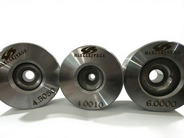
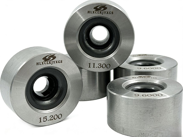
The wire surface is formed as the wire passes through the die bore. The surface that the wire sees—the bearing zone surface of the die—is reproduced on the wire surface, compressed and sheared by the drawing process but fundamentally a replica of the die bore surface. This is why the die bore surface finish is the primary determinant of wire surface finish.
The bearing zone is the final section of the die that the wire passes through before exiting. It is a short cylindrical section—typically 0.05 to 0.3mm in length for fine gauge dies—where the wire has already undergone the bulk of its deformation and is being sized to its final diameter. The surface of this zone is in contact with the wire surface for the entire bearing length, and every feature on the bearing zone surface leaves its imprint on the wire. Microgrooves from polishing scratches, embedded particles from inadequate cleaning, microscopic pitting from corrosion or chemical attack—these all appear on the drawn wire surface.
The relationship between die bore surface roughness and wire surface roughness is not one-to-one. The drawing process modifies the wire surface relative to the die bore surface. At high drawing speeds with good lubrication, the wire surface is typically smoother than the die bore surface because the plastic deformation of the wire surface fills in fine scratches and smooths out minor surface irregularities. At low speeds or with poor lubrication, the wire surface replicates the die bore surface more directly and may even be rougher if metal-to-metal contact creates adhesive wear patterns.
Surface Roughness Measurement and Specification
Surface roughness on drawn wire is measured as Ra—the arithmetic average of the surface height deviations from the mean line—typically expressed in micrometers or microinches. For most industrial wire applications, Ra in the range of 0.2 to 0.8 micrometers (8 to 32 microinches) is acceptable. For high-quality applications—automotive fasteners, medical wire, precision springs—Ra below 0.2 micrometers (8 microinches) may be required. For electrical wire and magnet wire, the surface roughness specification may be driven by insulation adhesion requirements rather than pure cosmetic quality.
Specifying drawing die surface finish requires specifying the bearing zone surface roughness and the acceptable bearing zone defect criteria. A surface roughness specification without defect criteria is incomplete because a die with Ra 0.05 micrometers and a single 1-micrometer scratch will produce wire with that scratch replicated thousands of times along its length—far worse than a die with Ra 0.15 micrometers and no scratches. The defect specification should define the maximum acceptable deterministic feature size on the bearing zone surface, expressed as a scratch depth or diameter.
The surface roughness measurement of a die bore requires specialized equipment. Standard tactile profilometers have styluses too large to measure inside a 0.5mm diameter bore. White light interferometry and confocal microscopy can measure bore surface roughness at the necessary scales, but the measurement must be performed by someone with experience positioning the instrument on the curved bore surface. A drawing die supplier who cannot provide surface roughness data for their dies is selling a product they have not fully characterized.
Die Material and Its Effect on Achievable Surface Finish
The die material determines the surface finishes that are achievable and the rates at which those finishes degrade during production. Different die materials have different grain structures, different hardness profiles, and different susceptibilities to the wear and chemical mechanisms that degrade bore surface quality.
Tungsten carbide is the most widely used drawing die material for gauges above approximately 0.3mm. The achievable surface finish with carbide depends on the carbide grade—the cobalt binder content and the tungsten carbide grain size. Fine-grain carbide grades (grain sizes below 2 micrometers) can be polished to Ra 0.05 to 0.10 micrometers in the bearing zone. Standard carbide grades with larger grain sizes cannot achieve this level of finish because the grain boundaries are visible at the necessary magnification and create a surface texture that limits the achievable smoothness.
The wear rate of the polished carbide surface depends on the drawing conditions. In clean, well-lubricated drawing of non-abrasive materials, the polished surface can maintain its finish for tens or hundreds of kilometers of wire production. In drawing of abrasive materials—steel with oxide scale, copper with surface contamination, or any wire with hard particle inclusions—the polished surface degrades faster as the abrasive particles impact and scratch the bore surface. Tracking the wire surface roughness over production output identifies the die wear rate for the specific application.
Polycrystalline Diamond Dies for Superior Surface Finish
Polycrystalline diamond (PCD) dies are specified when the surface quality requirements exceed what carbide can reliably deliver—typically for gauges below 0.3mm and for applications requiring Ra below 0.05 micrometers. PCD can be polished to smoother surfaces than carbide because the diamond grain structure is finer and more uniform, and because diamond is harder and more resistant to the scratching and embedding that degrades carbide bore surfaces.
The surface finish achievable with PCD is limited by the PCD grain size. Standard PCD grades with diamond grain sizes of 10 to 25 micrometers are used for wear applications but cannot be polished to the surface finish required for fine wire drawing. Micrograin and nanometer-grain PCD grades—with diamond grain sizes below 5 micrometers—are specifically manufactured for fine wire drawing applications and can be polished to Ra 0.01 to 0.03 micrometers in the bearing zone. These grades are more expensive than standard PCD but deliver the surface quality that fine gauge and high-quality applications require.
The primary limitation of PCD is fracture toughness. Diamond is hard but brittle, which makes PCD dies more sensitive to impact damage and handling damage than carbide dies. A PCD die that is dropped or struck can crack, and a cracked die will produce wire with surface defects until it is replaced. PCD dies require more careful handling procedures than carbide dies, particularly for the smallest gauges where the die blank is thinner and more vulnerable.
Die Geometry Effects on Wire Surface Formation
Beyond surface finish, drawing die geometry affects how the wire surface forms during the drawing process and the residual surface conditions that result. The approach angle, reduction profile, and bearing length all influence the surface quality of the drawn wire.
The approach angle determines how the wire enters the deformation zone and how the reduction is distributed as the wire cross-section decreases. An approach angle that is too shallow forces the deformation into a longer zone, increasing the contact area and friction force and potentially creating surface damage from excessive heat generation. An approach angle that is too large concentrates the reduction in a shorter zone, creating high local strain rates and potentially causing surface tensile stresses that lead to surface cracking or central burst.
The reduction profile—the shape of the transition from the approach zone to the bearing zone—affects the strain distribution in the wire surface layer. A smooth, well-designed reduction profile produces uniform strain in the surface layer without creating excessive tensile stresses at the surface. A poorly designed profile with a sharp transition or irregular shape can create localized tensile stresses that lead to surface defects even when the bearing zone surface is in perfect condition.
Bearing length affects the final sizing of the wire and the residual stress state of the surface layer. A bearing that is too long increases friction and heat generation without improving surface finish. A bearing that is too short does not provide enough distance for the wire surface to stabilize after the reduction, leaving residual stresses that can affect downstream processing or the final product performance.
Back Relief Geometry and Wire Exit Surface Quality
The back relief—the geometry at the exit end of the die—affects the wire surface as it exits the die bore. An inadequate back relief creates a stress concentration at the exit point that can cause microcracking or surface deformation in the wire. It also affects the wear pattern on the die, concentrating wear at the bearing exit and creating a wear groove that degrades dimensional control and surface finish over time.
A properly designed back relief provides a gradual transition from the bearing zone to the exit, reducing the stress concentration and distributing the exit wear over a wider area. The back relief geometry is typically specified as an included angle and length, with values that depend on the wire material, gauge, and drawing speed. The back relief design must be optimized for the specific application—back relief that is appropriate for steel wire drawing may be inadequate for copper or aluminum due to the different material behaviors at the die exit.
Lubrication and Its Interaction with Die Surface Quality
The drawing die surface finish is maintained only if the lubrication system prevents metal-to-metal contact between the wire and the die bore. A perfectly polished die bore will degrade rapidly if the lubrication film ruptures and allows the wire surface to make direct contact with the die. The lubrication system and the die surface are interdependent—good lubrication protects the die surface; good die surface quality enables good lubrication by maintaining a consistent geometry that the lubrication film can support.
Emulsion lubrication is the standard approach for most wire drawing applications. The emulsion must deliver three functions simultaneously: hydrodynamic lubrication during normal drawing, boundary lubrication when the film is thin, and heat removal from the die wire interface. The emulsion concentration, temperature, and cleanliness all affect the stability of the lubrication film. An emulsion that is too dilute provides inadequate boundary lubrication; one that is too concentrated creates excessive foam and poor heat removal. Bacterial contamination degrades emulsion performance by consuming the emulsifiers and producing acidic byproducts that attack both the die and the wire surface.
Die wall lubrication arrangements—felt pads, lubrication cores, or direct spray systems—supplement the emulsion by applying lubricant directly to the die entry zone where the wire enters the die. These systems are particularly important in fine gauge drawing where the lubrication film is thinner and more vulnerable to rupture. The lubrication core or felt pad should be maintained to ensure consistent lubricant delivery throughout the production run.
Die Wear Patterns and Their Effect on Wire Surface Quality
Drawing die wear manifests on the wire surface as progressive degradation in surface finish—fine die lines appearing and intensifying, surface roughness increasing beyond specification, and ultimately visible scratches that cause product rejection. The wear pattern on the die bore and the corresponding surface defects on the wire are diagnostic tools that help identify the wear mechanism and guide corrective action.
Uniform wear—where the bearing zone surface degrades evenly around the circumference—is the expected wear pattern for well-lubricated drawing. It produces wire with gradually increasing surface roughness, which allows the die change point to be predicted from production data and planned before the specification limit is exceeded. Uniform wear is managed by tracking surface roughness against production output and replacing the die when the surface quality approaches the specification limit.
Localized wear—where specific sections of the bearing zone wear faster than others—indicates a problem with die geometry, lubrication distribution, or wire alignment. Wear concentrated at the bottom of the bore indicates the wire is running low in the die, typically from inadequate top control or misaligned guides. Wear concentrated on one side indicates wire-to-bore contact from lateral movement, usually from vibration or inadequate guide alignment. Identifying the wear pattern and its cause allows corrective action to be taken before the localized wear creates significant quantities of defective wire.
Adhesive wear patterns—material from the wire embedded in the die bore—indicate lubrication film failure. The embedded material creates raised spots in the bore that scratch the wire surface until the embedded material is removed. Adhesive wear is managed by improving the lubrication system, adjusting the drawing speed or reduction to reduce the likelihood of film rupture, and by die maintenance to remove embedded material when it occurs.
Specifying Dies for Surface-Critical Applications
For applications where drawing die surface finish is critical to the product performance, the die specification should explicitly define the surface quality requirements and the verification methods used to confirm they are met.
The die specification should include the bearing zone surface roughness target (Ra, maximum), the acceptable deterministic defect criteria (maximum scratch depth and width), the die material and grade specification, and the required surface finish verification data. The verification data should include surface roughness measurements at multiple points in the bearing zone and a visual inspection report under magnification.
For the most demanding applications—medical wire, magnet wire, high-cycle fatigue wire—a production trial with the new die is the ultimate qualification test. Drawing wire through the die and measuring the wire surface roughness and inspecting for defects under magnification confirms that the die delivers the specified surface quality in actual production conditions. A die that passes dimensional and surface finish inspection but fails the production trial should not be accepted for surface-critical applications.
Frequently Asked Questions
Q1: What surface roughness can be achieved with tungsten carbide drawing dies?
Fine-grain tungsten carbide dies can be polished to Ra 0.05 to 0.10 micrometers in the bearing zone. Standard carbide grades with larger grain sizes can achieve Ra 0.10 to 0.20 micrometers. For applications requiring smoother surfaces, PCD dies are specified. The achievable finish also depends on the die size—very small dies are more difficult to polish to tight roughness specifications.
Q2: How does die wear affect wire surface finish?
Die wear degrades wire surface finish by roughening the bearing zone surface and creating deterministic defects—scratches, pits, and embedded material—that appear on the wire surface. The rate of degradation depends on the drawing conditions, the wire material, and the die material. Tracking wire surface roughness against production output identifies the die change point for surface-critical applications.
Q3: What is the difference between PCD and carbide surface finish capability?
PCD dies can be polished to smoother surfaces than carbide because the diamond grain structure is finer and more uniform. Micrograin PCD grades can achieve Ra 0.01 to 0.03 micrometers in the bearing zone, compared to 0.05 to 0.10 micrometers for fine-grain carbide. PCD also maintains its surface finish longer in production because diamond is harder and more wear-resistant than carbide.
Q4: How does lubrication affect die surface finish?
Lubrication protects the die bore surface by preventing metal-to-metal contact between the wire and the die. When the lubrication film ruptures, direct contact causes adhesive wear—wire material embedding in the die bore—and creates scratches on both the die and the wire surface. Maintaining proper emulsion concentration, temperature, and cleanliness is essential for preserving the die bore surface finish over production runs.
Q5: Can a die with good initial surface finish produce poor wire surface finish?
Yes. A die with excellent initial bore surface finish can produce poor wire surface if the lubrication system fails, if the die geometry is wrong for the application, or if wire handling downstream of the die damages the surface. Die surface finish is necessary but not sufficient—good wire surface finish requires good lubrication, correct die geometry, and proper wire handling throughout the production line.
Conclusion
The drawing die surface finish is a critical specification that determines the surface quality of the drawn wire and, for many applications, the performance of the finished product. The die bore surface acts as a template that is replicated on the wire surface, and every feature on the die bore—polishing scratches, embedded particles, wear patterns—appears on the wire. Selecting the right die material and grade for the surface quality requirements, specifying the surface finish and defect criteria explicitly, and maintaining the lubrication system that protects the die surface during production are all essential to delivering wire that meets the surface quality specifications that surface-critical applications demand.
References
Richardson, J. H., & Martinez, C. A. (2023). Die Wear Mechanisms in Wire Drawing: Effects of Lubrication Regime and Die Material. Wear, 518-519, 204618.
Zhang, Y., & Liu, W. (2023). Surface Finish Optimization for PCD Dies in Ultra-Fine Wire Drawing. Precision Engineering, 78, 234-245.
ASTM International. (2023). Standard Specification for Polycrystalline Diamond Dies for Wire Drawing (ASTM B963-23). West Conshohocken, PA.
Wright, R. N., & Bae, N. (2023). Lubrication Mechanisms in Fine Wire Drawing Processes. Journal of Manufacturing Science and Engineering, 145(6), 061010.
ASM International. (2022). Friction, Lubrication, and Wear Technology (2nd ed.). Materials Park, OH: ASM International.