Current location:
Custom Profile Extrusion Mold Design for Industrial Applications
2026-09-22Standard extruded profiles—circular rod, standard pipe, simple square section—can be produced with dies designed from established geometries and known flow behavior. When the profile is non-standard—a complex window frame with multiple hollow chambers, an industrial rail with specific mechanical attachment features, an automotive trim section with a decorative surface on one face and a structural function on another—the die cannot be selected from a catalog. It must be engineered from the material's rheological properties, the target production rate, and the specific geometry of the product cross-section. That engineering process is what makes custom profile extrusion mold design a specialized discipline—and why the choice of a die manufacturer matters as much as the product design itself.
When Custom Profile Extrusion Dies Are Required
Most extruded profiles begin as standard shapes because standard dies are faster to produce, less expensive to qualify, and easier to source from multiple suppliers. The decision to invest in a custom profile extrusion die is driven by application requirements that standard shapes cannot meet.
Functional complexity is the most common driver. A profile that must serve structural, thermal, acoustic, and aesthetic functions simultaneously rarely has a standard cross-section that satisfies all of them. An aluminum window frame must carry structural loads, seal against weather infiltration, accommodate hardware attachments, and present a finished surface. A single cross-section must accommodate all of these requirements, which means it cannot be standard—and neither can the die that produces it.
Space and weight optimization in machinery and automotive applications drives custom profile design in a different direction. These applications often need profiles with the highest stiffness-to-weight ratio, which requires topology-optimized cross-sections with thin walls, internal ribs, and complex hollow chambers. Producing these sections requires dies that can distribute polymer flow into geometries that are fundamentally challenging to fill uniformly.
Brand differentiation in consumer-facing applications—architectural extrusion, consumer product profiles—creates demand for unique cross-sections that cannot be reproduced by competitors using standard shapes. The custom profile die is as much a competitive tool as a manufacturing tool in these applications, and the die manufacturer must understand both the production requirements and the commercial value of the profile shape itself.
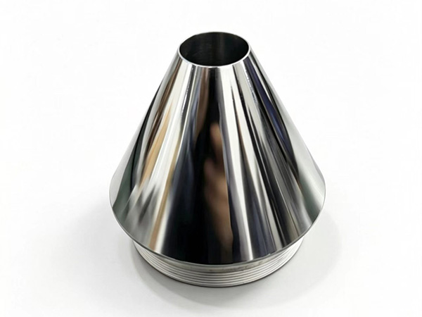
Die Geometry Design for Non-Circular Profiles
The fundamental challenge in custom profile extrusion die design is achieving uniform flow distribution through a non-circular opening. In a circular tube die, the symmetry ensures that every path from the inlet to the exit has the same length and flow resistance. In a complex profile, the paths are different lengths, and the die geometry must compensate for these differences to produce uniform output.
The die land is the first design parameter to address. The land length—the straight section of the die bore before the exit—determines the pressure drop and the flow conditioning that occurs before the material exits. A longer land provides more pressure drop and better flow smoothing, which helps compensate for minor flow inequalities. A shorter land reduces pressure drop and material residence time, which matters for temperature-sensitive polymers. For custom profiles, the land length is typically optimized through simulation and adjusted based on production trials.
The flow distributor or transition zone upstream of the die land is where the polymer flow from the extruder screw is redistributed into the profile geometry. This zone is the critical engineering element in a custom profile extrusion die. The distributor must slow fast-moving flow from the center of the extruder barrel, accelerate flow to thinner sections of the profile, and distribute material to every point in the profile cross-section at the correct rate. The design is typically developed using CFD simulation validated against prototype production trials.
Wall Thickness Variation in Complex Profiles
Complex profiles inherently have sections of different wall thickness—thin decorative features alongside thick structural ribs. The thicker sections require more material flow per unit time than the thinner sections, but they also have higher thermal mass and cool more slowly. The die geometry must balance flow rate against cooling rate to ensure that all sections reach their final dimensions simultaneously.
A practical approach is to specify the maximum acceptable wall thickness variation in the finished profile—typically expressed as a percentage of the nominal thickness—before the die design begins. This specification constrains the design space and determines how much flow redistribution the die must achieve. A profile requiring ±5 percent thickness tolerance is substantially easier to design than one requiring ±2 percent, which affects die complexity, cost, and the number of adjustment mechanisms required in the production die.
Material Selection for Custom Profile Extrusion Dies
The die material must be matched to the polymer being processed and the production volume expected from the tooling. A custom profile extrusion die represents a significant engineering investment, and the material selection should be based on the total cost of ownership over the die's production life, not just the initial tooling cost.
Tool steel remains the baseline material for custom profile extrusion dies. It machines well, can be polished to good surface finishes, and costs less than specialty materials. For commodity polymer extrusion—PVC window profiles, standard polyethylene products—at moderate production volumes, tool steel provides adequate performance. The wear rate in abrasive compounds or high-volume production will eventually require refurbishment, but the initial cost advantage often justifies the choice.
Hard metal or tungsten carbide inserts are used in high-wear zones of custom dies processing mineral-filled compounds, glass fiber reinforcement, or flame-retardant additives that accelerate wear on tool steel. The inserts are typically placed in the flow channels and die land surfaces that experience the highest wear rates, with tool steel bodies supporting the inserts. This hybrid construction balances cost against wear resistance where it matters most.
Stainless steel and corrosion-resistant alloys are required for PVC extrusion and other halogenated polymers that generate corrosive byproducts during processing. Hydrochloric acid generated during PVC extrusion attacks standard tool steel dies, degrading surface finish and dimensional accuracy within weeks of production. A die manufacturer who specifies tool steel for PVC extrusion without surface protection or corrosion-resistant construction is creating a reliability problem for their customer.
Surface Treatments and Coatings
PVD coatings—chromium nitride, titanium nitride, and similar treatments—extend die life and improve surface quality in demanding applications. The coating reduces material adhesion to the die surface, which is particularly valuable when switching between different polymer grades or colors. A coated die cleans more easily, maintains surface finish over longer production runs, and resists the micro-adhesion that causes surface defects in high-gloss extrusion.
The decision to apply coatings should be based on production volume, surface quality requirements, and material change frequency. A die producing high-volume PVC window profiles benefits significantly from chrome nitride coating because the production run lengths justify the coating cost. A die producing small-lot custom profiles in multiple materials may not justify the coating expense if the die will be stripped and recoated between each material run.
Cooling System Integration in Custom Profile Dies
Cooling in profile extrusion is not a downstream process separate from the die—it is integrated into the die head assembly and must be designed concurrently with the flow geometry. A die with excellent flow distribution but poor cooling integration will not produce consistent product because the thermal profile will vary across the die opening as material flows through it.
The cooling channels in a custom profile extrusion die must be positioned to remove heat from the die at rates proportional to the local polymer flow rate and wall thickness in the profile. Sections of the profile with thicker walls have more thermal mass and require more cooling per unit time than thin sections. The cooling channel layout must account for these differences, which in complex profiles means the channel routing can be as complex as the profile geometry itself.
For multi-cavity custom dies—where the die produces multiple profiles simultaneously—cooling balance is critical. Each cavity must receive the same heat removal rate relative to its polymer throughput, or the profiles will emerge with different dimensions and surface qualities. Die cooling balance is typically verified through thermal simulation during the design phase and adjusted through flow balancing in the cooling system during production.
Die Adjustment Mechanisms for Dimensional Control
A newly commissioned custom profile extrusion die rarely produces acceptable product without adjustment. The die must be tuned to the specific material grade, the specific extrusion rate, and the ambient conditions of the production facility. Die adjustment mechanisms are designed into the tooling to enable this tuning without modifying the die body itself.
Adjustable die lips are the primary tuning mechanism for profile dimensions. The lips at the die exit—the final shaping edges that define the profile outer contour—can be moved inward or outward to adjust the gap at specific points. This adjustment compensates for dimensional drift from thermal expansion, material variability, or process fluctuations during production. The adjustment range is typically small, which is why die design accuracy is so important: adjustment mechanisms are for fine-tuning, not for correcting fundamental design errors.
Flow control baffles inside the die allow the distribution of polymer flow to different sections of the profile cross-section to be adjusted. A baffle that restricts flow to a section that runs oversized, for example, can bring that section into tolerance without modifying the die body. The baffle adjustment mechanism typically uses a fine-threaded adjustment screw that provides micrometer-scale positional control.
Custom Profile Extrusion Applications Across Industries
The custom profile extrusion mold serves applications across a wide range of industrial sectors, each with its own requirements for profile geometry, material performance, and production economics.
Construction and architecture represent the largest volume segment for custom profile extrusion. Aluminum and PVC profiles for curtain wall systems, window frames, and architectural trim require complex cross-sections that accommodate structural loads, thermal breaks, weather sealing, and hardware attachment simultaneously. The die designs for these profiles are highly refined through decades of iteration, but each new architectural design requires a new die.
Automotive interior and exterior trim uses custom extruded profiles in PVC, TPO, and ABS for applications ranging from window seals to dashboard trim to structural reinforcement. These profiles require tight dimensional tolerances for fit and appearance, and the dies must produce consistent surface quality across long production runs. Automotive profiles are often specified with multiple color layers or integrated coextrusion, which adds complexity to the die design.
Industrial machinery and equipment applications use custom profiles in engineering polymers—nylon, acetal, polycarbonate, PVDF—for components that require specific mechanical, thermal, or chemical properties. The extrusion die must be designed for the specific rheology of the engineering polymer, which often has different flow characteristics than commodity materials. Engineering polymer extrusion dies are typically more expensive than standard polymer dies because of the tighter tolerances and more demanding material behavior.
Evaluating a Custom Profile Extrusion Die Manufacturer
Sourcing a custom profile extrusion die requires evaluating the manufacturer on engineering capability, not just tooling price. The die is a capital investment that determines the quality and productivity of the production line for years, and the engineering depth behind the design matters as much as the machining quality.
Design capability assessment should include the manufacturer's CFD or simulation tools for flow distribution analysis, their experience with the specific polymer family being processed, and their process for prototype trials and design refinement before final die approval. A manufacturer who provides no prototype testing and promises that the first die will be production-ready is transferring too much risk to the buyer.
Material and quality documentation should include material certificates for the die body and insert materials, heat treatment specifications, surface finish measurement data, and dimensional inspection reports for the finished die. The manufacturer should be able to provide process capability data for the critical die dimensions if requested.
Frequently Asked Questions
Q1: What is the typical lead time for a custom profile extrusion die?
Lead times for custom profile extrusion dies range from 4 to 12 weeks depending on the complexity of the profile geometry, the die material specification, and the manufacturer's current capacity. Simple single-cavity dies in tool steel can be produced in 4 to 6 weeks. Complex multi-cavity dies or dies requiring hard metal inserts may require 8 to 12 weeks. The prototype trial and adjustment phase adds additional time after the initial die is delivered.
Q2: How do I specify wall thickness tolerance requirements for a custom profile die?
Specify the tolerance as a percentage of the nominal wall thickness for each critical section of the profile. A typical industrial profile specification might require ±10 percent on thick sections and ±15 percent on thin sections, with tighter tolerances on functional surfaces where dimensional variation affects assembly or performance. Communicate these requirements to the die manufacturer early so the die geometry can be optimized for the specified tolerances.
Q3: Can a custom profile die be modified to produce a similar profile?
Some modifications are feasible: adjusting die lips, adding or repositioning flow control baffles, and modifying the die land geometry are common die modifications. Significant geometry changes—different wall thickness distribution, additional profile features, substantially different cross-sectional area—typically require a new die. A die manufacturer can assess whether an existing die can be adapted and provide a cost comparison between modification and new tooling.
Q4: What surface finish can be achieved on a custom profile extrusion die?
Custom profile extrusion dies can be produced with bearing surface finishes from Ra 0.2 to 0.8 micrometers depending on the polymer and surface quality requirements. High-gloss products require dies polished to Ra 0.1 to 0.2 micrometers, which requires fine-grain tool steel or hard metal inserts with specialized polishing. Matte-finish products can use dies with Ra 0.4 to 0.8 micrometer finishes that are faster and less expensive to produce.
Q5: What information should I provide when requesting a custom profile extrusion die quotation?
Provide the profile drawing with all critical dimensions and tolerances, the target polymer material and grade, the expected production volume and run length, the extrusion rate requirement, the surface finish specification, and any special requirements such as coextrusion, multi-color, or FDA compliance. The more complete this information is, the more accurate the quotation and the better the die design will match the application requirements.
Conclusion
Custom profile extrusion mold design is an engineering discipline that combines polymer rheology, thermal management, and precision manufacturing to produce tooling that shapes complex cross-sections consistently at production rates. The die geometry must be designed for the specific profile, the specific material, and the specific production requirements—no standard die works for non-standard profiles. Working with a die manufacturer who brings engineering analysis to the design process, not just machining capability, delivers tooling that performs consistently from the first production run and maintains that performance over years of production. The investment in proper engineering upfront pays back through better product quality, higher production yield, and fewer die-related production disruptions.
References
Michaeli, W. (2022). Extrusion Dies for Plastics and Rubber: Design and Engineering Computations (4th ed.). Munich: Hanser Publications.
Dealy, J. M., & Savant, D. C. (2023). Structured Fluids: Polymers, Colloids, Surfactants. Oxford University Press.
Chung, D. H., & Lee, J. H. (2023). Flow Distribution in Complex Profile Extrusion Dies: CFD Simulation and Experimental Validation. Journal of Materials Processing Technology, 314, 117922.
ASTM International. (2023). Standard Practice for Determination of Die Wall Temperature and Heated Length of Extruders (ASTM D1238-23). West Conshohocken, PA.
Robinson, M., & Zhang, H. (2022). Wear Mechanisms in Extrusion Dies Processing Mineral-Filled Polymer Compounds. Polymer Engineering & Science, 62(8), 2456-2468.