Current location:
Best Drawing Dies for Copper Wire Production: A Complete Guide
2026-07-31Copper wire drawing puts unique demands on tooling that steel and aluminum producers never have to think about. The material is soft enough to draw at high speeds, but soft enough that surface defects transfer instantly from the die bore to the wire surface—meaning every scratch, every particle, every wobble in the die geometry shows up on the finished conductor. Getting copper wire drawing dies right is less about brute-force wear resistance and more about achieving a combination of low friction, minimal heat generation, and mirror-quality bore finish that no other wire material quite demands in the same way. This article is for production managers and procurement leads at copper wire mills who want to understand what separates the dies that run smoothly for weeks from the ones that generate scrap calls and customer complaints from day one.
Why Copper Wire Draws Differently From Other Materials
When a copper rod enters the die bore, something subtle happens that does not occur with steel. The copper surface, even when it looks perfectly clean, carries a thin oxide layer that interacts with the die surface under the extreme pressure of drawing. If the die bore is not polished to a sufficiently low roughness value, the oxide layer fragments and leaves microscopic scratches that grow into surface defects as the wire progresses through subsequent passes.
Heat is another factor. Copper has excellent thermal conductivity—nearly ten times that of steel—which means frictional heat at the die interface dissipates more readily into the wire itself. This sounds like an advantage, but it creates a thermal gradient within the die that causes bore expansion and contraction as drawing speed varies. Dies that are not designed with this thermal behavior in mind develop taper and lose diameter control when the mill operator speeds up for a large order.
The combination of soft surface, high drawing speeds, and thermal cycling means that the best drawing dies for copper wire production are not simply the hardest available—they are the ones engineered specifically for copper's behavior profile.
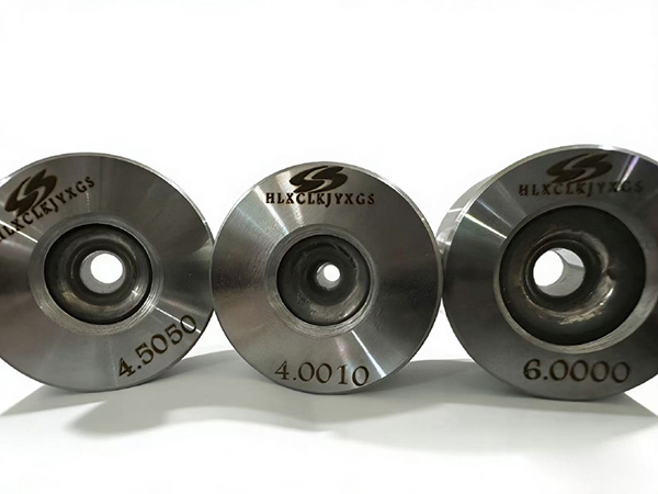
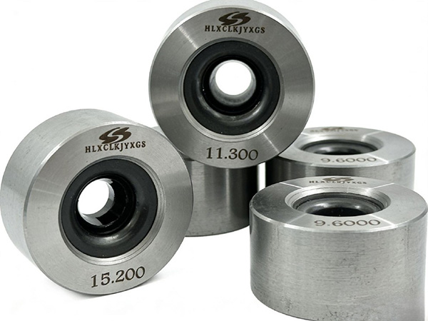
PCD Dies: Why They Dominate Copper Magnet Wire Applications
The copper magnet wire industry—wire destined for motor windings, transformer coils, and electromagnetic devices—has largely converged on polycrystalline diamond dies as the standard tooling. This is not an accident. PCD dies offer a combination of properties that copper magnet wire producers simply cannot replicate with carbide.
PCD's diamond surface polishes to Ra values below 0.05 micrometers, which is smooth enough that the copper surface never contacts anything rough enough to fragment the oxide layer or generate scratches. The intergranular cobalt structure that holds PCD together provides fracture toughness sufficient to handle the occasional wire break or threading shock without cracking. And diamond's thermal conductivity of 200 to 400 watts per meter-Kelvin carries heat away from the die interface far more effectively than any carbide can manage.
A factory running high-speed copper magnet wire drawing at 800 to 1200 meters per minute will typically see PCD die service life three to five times longer than equivalent carbide dies, with significantly lower scrap rates during the first hours of operation when new dies are bedding in. The premium cost of PCD is justified for any mill drawing fine copper wire at volume.
Carbide Dies for Copper: When They Make Sense
Not every copper wire application justifies the cost of PCD. Coarser copper conductors—wire above 2 millimeters in diameter used for power cable, building wire, and earthing applications—can often be drawn effectively with tungsten carbide dies designed and polished to copper-specific standards.
The key adjustment for carbide in copper applications is surface finish. A standard carbide die polished to Ra 0.15 micrometers is adequate for structural copper but not for magnet wire. For electrical conductor applications, a supplier who specializes in copper will typically polish to Ra 0.08 to 0.12 micrometers—a modest extra step that dramatically reduces the break-in scrap period when a new die goes into production.
Carbide grade selection also matters. Finer-grain carbides (0.5 to 1.0 micrometer grain size, 6 to 10 percent cobalt content) provide the combination of hardness and polishability that copper drawing demands without the excessive brittleness of very fine grades. A manufacturer who understands copper will recommend this grade range rather than the coarser grades they might use for steel wire.
Die Geometry Adjustments for Copper Drawing
The geometry of copper wire drawing dies deserves more attention than it usually gets. Standard approach angles designed for steel wire are frequently too steep for copper, causing the material to deform unevenly at the die entry and generating centerburst defects in subsequent passes.
A shallower approach angle—typically 12 to 18 degrees included angle versus the 20 to 26 degrees common for steel—reduces the deformation severity at entry and allows the copper to flow more uniformly into the reduction zone. The bearing length should be proportionally shorter as well, since copper's low friction coefficient means less material needs to be sized by the bearing surface before the wire exits.
Suppliers who engineer custom geometries for copper applications understand these adjustments automatically. A factory that buys standard off-the-shelf dies without specifying copper-optimized geometry is accepting geometry that was designed for a different material and may not perform optimally for their production.
Lubrication Interaction With Copper Die Performance
Copper wire drawing relies entirely on wet lubrication—emulsion-based lubricants that cool the die and wire while providing boundary film between the copper surface and the die bore. The lubricant formulation, concentration, and temperature all interact with die performance in ways that procurement decisions rarely account for.
Lubricant concentration matters more than most mills realize. Too much soap content in the emulsion increases viscosity and can cause die line defects from uneven film thickness. Too little concentration allows metal-to-metal contact and accelerates adhesive wear on the die bore. Most copper wire suppliers target 3 to 8 percent concentration depending on drawing speed, with tighter control at higher speeds.
A die supplier who understands copper applications will ask about your lubricant system during consultation. Dies designed with one lubricant type in mind may not perform the same way with a different formulation. This is not a reason to change lubricants, but it is a reason to share that information with your tooling partner.
Common Copper Die Problems and How to Identify Their Causes
Production issues with copper wire drawing dies tend to fall into a recognizable pattern. Knowing which symptom indicates which root cause saves significant troubleshooting time.
Centerburst cracking—longitudinal fractures appearing in the wire center during drawing—typically points to excessive reduction per pass or an approach angle too steep for the material ductility at that reduction. Reducing the reduction ratio or switching to a shallower approach angle resolves it.
Die lines running the length of the wire usually indicate bore surface contamination: lubricant debris, copper oxide particles, or polishing compound residue in the bearing zone. Dies that develop die lines within the first hour of use often have residual polishing compound that was not fully cleaned before shipping.
Rapid bore polishing loss—die lasting only a fraction of expected life—typically means the lubricant is breaking down or the die surface is not being properly maintained between runs. It can also indicate a carbide grade that is too soft for the drawing speed being used.
Frequently Asked Questions
Q1: What is the minimum wire diameter where PCD dies become cost-effective for copper?
For most copper wire mills, PCD dies become economically justified below 1.0 millimeters diameter when monthly production volume exceeds 50,000 kilograms. Below 0.5 millimeters, PCD is almost always the correct choice regardless of volume, because carbide cannot hold the required surface finish long enough to be economical.
Q2: Can I use the same die for oxygen-free copper and standard ETP copper?
The two copper grades draw similarly, but oxygen-free copper's superior surface cleanliness reduces the risk of die line defects. A die that works well for OFHC should also perform for ETP, but the reverse is not always true. Avoid mixing grades in the same die without checking surface condition between runs.
Q3: How does drawing speed affect die selection for copper wire?
Speeds above 800 meters per minute favor PCD because its thermal conductivity prevents the die bore temperature from climbing to levels that cause surface degradation. At moderate speeds (300 to 800 m/min), a well-polished carbide die often performs adequately. Below 300 m/min, standard carbide is usually sufficient.
Q4: How should I clean copper drawing dies between production runs?
Ultrasonic cleaning in a mild alkaline solution removes lubricant residue and copper oxide particles from the bore without damaging the surface finish. Avoid abrasive cleaning methods that could scratch the bearing zone. A supplier who provides proper cleaning instructions with their dies can significantly extend effective die life.
Q5: What signs indicate a copper drawing die needs replacement rather than reconditioning?
Replace when bore surface roughness has degraded beyond the application requirement (even after repolishing), when concentricity between bore and shell has shifted beyond tolerance, or when the bearing zone shows visible rounding from wear. Recondition when geometry is still within tolerance but surface polish has degraded.
Conclusion
Selecting the best drawing dies for copper wire production requires matching die material, geometry, and surface finish to the specific demands of copper's behavior profile. PCD dies are the right choice for fine magnet wire and high-speed applications where surface quality and thermal management are paramount. Carbide dies, properly specified for copper, handle electrical conductor and coarse copper wire economically. Geometry should be tailored to copper's deformation characteristics rather than borrowed from steel-drawing practice. Work with a die supplier who understands these distinctions and engineers their copper dies accordingly. The right tooling choice, combined with proper lubricant management and die maintenance practices, transforms copper drawing from a source of chronic quality problems into a reliable, high-performance production process that satisfies the most demanding customers in the electrical industry.
References
Park, S., & Martinez, C. (2023). Surface Finish Requirements for PCD Dies in High-Speed Copper Magnet Wire Drawing. Journal of Materials Processing Technology, 312, 117849.
Chen, Y., & Thompson, R. (2022). Thermal Management Strategies in Copper Wire Drawing with Diamond Dies. International Journal of Advanced Manufacturing Technology, 121(9-10), 6234-6248.
Williams, P., & Lee, J. (2023). Lubricant System Optimization for Fine Copper Wire Drawing Operations. Wear, 518-519, 204728.
ASTM International. (2023). Standard Specification for Polycrystalline Diamond Dies for Wire Drawing (ASTM B963-23). West Conshohocken, PA.
Wire Association International. (2023). Technical Guidelines for Copper Wire Drawing Die Selection and Maintenance. Guilford, CT: WAI Publications.